Hey all!
Long time no post. Here's a short video talking about cracks and some other tips in substance designer:
Would you be interested in other topics I could cover this way?
Hey all!
Long time no post. Here's a short video talking about cracks and some other tips in substance designer:
Would you be interested in other topics I could cover this way?
Thanks for all the interest in my recent fan art of some Arcane materials! I got several requests to share the graph/make a tutorial so here goes...
I know some people prefer videos and others - written guides. You can go on and read this guide or watch the in-depth Youtube video HERE
You can download the graph for free here.
The video is a lot more in-depth and goes over the whole process, but if you just want a quick look - here goes:
If you want a bit more high-res images you can download the whole graph and the breakdown here: MARKETPLACE LINK
First off - a ref - always nice to have references!
The colours of the wall change up a bit depending on the scene and angles, so I chose something closer to the top one. The art style in Arcane is amazing and it's detail changes depending how close the camera is. We're going to be making something that's a bit far - similar to the top ref.
This here is the whole graph and we're gonna go step by step through it. There's also a secondary graph for the papers.
1. Bricks:
I'm keeping things super simple here. A tile generator and a flood fill. We get some Flood fill random grayscale, gradient and Shape mapper. The shape mapper uses a Polygon 2 multiplied with Clouds 2 for the input. This gets us some edge damage. Then there's some Slope blur, a bit of noise on top for detail and a Contrast/Luminosity to get our height value in check. This can be replaced by a Histogram Range if you prefer.
2. Plaster
The plaster looks a bit more complicated but it is rather simple. On the bottom left we have a generator, which is our main height. This can be any noise, I just chose a Shape and transformed it by hand - easily art directable. The top part is mostly hand placed damages, which become our holes. The main thing here is the 2 Histogram Scans in the MASKS box - Bottom one is the top concrete and top one is the middle concrete. There's a slight difference in the value, so we pick a bit more for the top one. Subtracting the 2 Histogram Scans will give us the middle concrete mask we want. We Blend those together, minding the height values, and blend with the bricks.
3. Blend plaster + bricks and add grout
Height Blend the bricks with the plaster. Simple and also gives us a mask. Then, invert that and histogram scan to get our grout. A bit of warping/slope blur, adding some Moisture Noise in the end for some detail. Blend that together with another Height Blend.
This is pretty much our final height map. There's only 1 more step, where I add the metal poster later on.
4. Creating the masks for brick colours
Here I'm reusing some noises I have in the graph and Slope Blurring them. Then Directional Warp with our bricks random grayscale values. We also had Flood Fill to Gradient for the bricks, so I'm using that as a Mask to add some color variation which has a bit of directionality. These are only used as masks for blending colours for the bricks.
5. Bricks Colour
I'm starting out with a Gradient Map with some handpicked colours(height map as input). Then I blend some Uniform Colours with the masks from the previous step. Some final colour variation from a grunge we will create in a bit in the plaster section. Then just blending that with the plaster.
6. Plaster Colour
Again, this seems a bit more complicated, but still quite simple. Most of the work here is done using a Grunge Map and directional/slope blurring it. Directional Blur adds a bit of gravity to the piece. RT Shadows gives the leaks under the holes in the concrete and under the metal poster. Anything you add to the RT Shadows input will generate some leaks. We invert it and blend that with a blurred Grunge for some variation. Moisture noise also helps out a bit with random splotches. Again, using mostly Uniform colours. Most of the variation comes from the masks used for blending.
7. Middle Plaster
This I kept extremely clean and simple. In the refs you can barely see any variation in the colour for this part. Adding just a bit of variation with the Gradient Map( using the Moisture noise from above) and using the leaks we made. For a simple trick - Transform 2D and offset the noise a bit so it's not the same. Cheap variation. ;)
8. Blend the colours
Here I'm blending all the components together and adding the papers at the end. The papers are in a separate graph and I'll go over that briefly in here.
9. Papers graph
I'll keep this brief in here and hopefully add a bit to it in the video tutorial. Most of the graph is just the big metal plate and the top right are the papers. Mostly using simple shapes and blending them together.
10. Plate Height
Starting with a Shape, square, scaled a bit. Edge Detect to round the edges a bit and Bevel to add some height. At the top we have a circle, transformed 4 times to get all the corners and subtract from the main shape. We then edge detect that to get the mask for the orange inside border from the ref.
11. Text and Circle
Circle is simple - shape(disc), edge detect and multi dir. warp grayscale. The text is pretty much the same, write some text, blend it together, blur and warp. The text isn't really readable in the refs so I just used a directional blur to smudge it. We can go wild here, it needs to HINT it's a text.
12. Leaks and grunges
Here we create some grunge for the colour. The bottom left is coming from Grunge Map 011. Rust/Leaks part is actually the text from the previous step. RT Shadows and blend with the grunge, then slope blur. Pretty similar to the leaks from the main graph. I also get that, warp it and blur it a bit more and use it as a subtle colour variation a few more times.
13. Final height
Small step, simply adding the rust/damage to the heighmap and transforming it into the correct place. This may be different for you, it should go on the top concrete.
14. Fake shadows/outline
There's a readable outline on some objects in the ref, so it's nice to add it here. Create a normal from the height, RGBA Split and use the R and G channels with a Levels. Top one will get us things facing right and the other one - things facing down. If you invert grayscale the channels you can get left or up. Then we blend those together and use it as a colour mask to add a shadow.
15. Big paper
I decided to go with 1 big paper, the metal plate and a group of 3 smaller papers. This part here is creating the big paper. Tearing,again, uses a Directional Blur. This sells the feel the paper's been torn.
16. Smaller papers
Pretty much the same as the big paper. In the ref those looked like they were destroyed together, so before subtracting I add them together. For the coloured border inside we actually need to use the intact papers, as otherwise we'll get weird results.
17. End
And that's it! We go back to the main graph and add the papers in the basecolour and height as the last step.
I've commented the graph and tried to organize it a bit. If there's any questions feel free to shoot them here or on Youtube!
Happy Holidays and have a great new year!

Been a long time since my last blog post! Nothing too technical this time around, just some patterns. :) A while back I tried some patterns and recently had to do some more at work. Thought it was time to try and go at it with some more effort.
 The main pattern that I created
So...first thing is - GET SOME REFERENCES! It doesn't matter if you go and copy it 1:1 or just use it for inspiration. Having a reference will help you along the way. When you're doing intricate patterns, chances are you're going to get a lot of nodes in your graph. Try to keep your colour nodes as few as possible. For this one I had 6 uniform colour nodes set to 16x16px. Don't get overwhelmed by all the different elements the pattern has! Break it 1 by 1, start center to edges or the other way around. Just don't jump around back and forth, as your graph will get messy and you won't be able to iterate easily.
I didn't use any special techniques here. It's just shape/polygon/transform/splatter circular/shape mapper. Yup, 5 kinds of nodes are enough to get the job done for pattern creation. Ok, there was a little trick to get the secondary colour for the crossing patterns, but let's keep it simple in this post. Here's a GIF to show the order in which I added each element:
 You can see at the end I'm going back a bit, but that's because I felt the pattern was a bit empty there.
Secondly, do you want to get more patterns out of your initial pattern? Because this is where the fun begins. This technique depends on symmetry and your overall pattern, but feel free to try it out and share your results! I think I got around 32 different patterns from the initial one above.

So, here are some different patterns, extracted from the main one. And again, not much going on here. It's mostly 2D Transform and a little trick with the Tile Generator. Let's see how this goes:

Imagine you pattern is subdivided in all those smaller areas. Each one of these areas holds a possibility to create a whole new pattern. How can we get these? Using a Transform 2D to scale up or down( x2 or /2), offsetting by 0.5 on x, offsetting by 0.5 on y or any combination of those. Also, we can offset by 0.25, but this requires the Tile Sampler trick to tile properly. Let's see some examples:
 Main Pattern offset by 0.5 on x and y
 Main Pattern scaled x2
 Main pattern scaled x2, then in another Transform 2D - offset by 0.5 on x and y
 Main pattern scaled x2, then in another Transform 2D - offset by 0.5 on x and y and scaled x2
With that said, there is something to keep in mind! Let's say we start off with a 2048 x 2048 image. The first time you do x2 you will be getting only 1024x1024 of detail. The second time 512x512 and so on. At some point you might see pixels. Is that an issue though?
An example: you create a tile generator that is 8 x 8 tiles. If your final resolution is 2048, each tile will be 2048/8 = 256 px. In this case you could have down-scaled the image once more to 256x256 and still have enough detail. Anything beyond that will be a loss.

So, that's the simple way to get tons of variation from your main pattern. It's important than you start with an intricate enough pattern to be able to break it down by sections. Now we can go and try offsetting by 0.25 and see what happens:
 This doesn't look right, does it? Notice on the Tile Generator there is a Quincunx Flip option. Here it's off.
 And here is the same thing, but with Quincunx flip on
There are probably other ways to get that result, but this seemed the simplest to me. You can generate a variation from your main pattern, then generate a variation from the variation and so on! As I said, I got about 32 patterns from this one. Here are some of them:


At the end of the day what matters is - how are you going to use those? You can easily use each pattern for some tile variation. You can Tile each pattern on it's own or use the already tiled patterns. Each one of those variations above is tileable. And, if you made your graph correctly and only used Uniform Colours, you can easily change the colour scheme of your pattern at any time.
This same technique could be easily applied to knitting patterns and other fabric patterns.
Something with those patterns: https://artstn.co/p/4bV9k4
Hope this has been useful!

Back for some FX-map tips. This time- adding additional functionality to existing nodes. Our target is the Splatter Circular. I won't be going into details how Allegorithmic set it up, but I'll try to explain how to identify what you need to modify and how, to actually make our improved node.
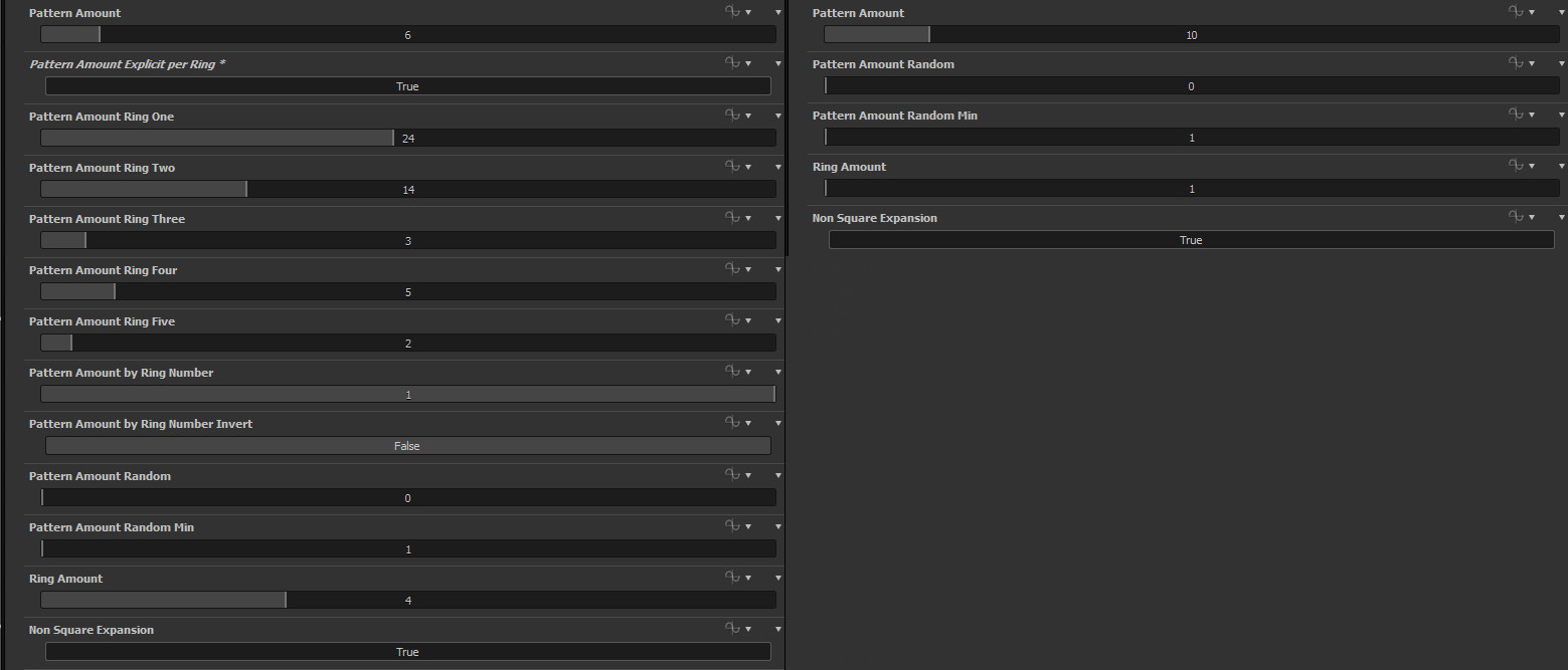
So, what are we doing? We want to control the Pattern Amount by our ring number and as a bonus- to explicitly state the Pattern Amount per ring(going up to ring 5 only, didn't think more was necessary). Our first control will be |Patter Amount * ring number|,giving us 0*n, 1*n, 2*n, 3*n and so on. I could've added a check not to have that 0 in there, but it still works fine without it, we just lose our first ring. The other control is pretty self explanatory, we set the Pattern Amount for each ring ourselves. That's what the UI of my edited Splatter Circular looks like:
First thing we need to do- study how the node is set up. It's not one of the easiest nodes and has quite some math in it. Starting top to bottom inside the FX-map is the way to go. Parameters set in topmost nodes can be re-used in bottom nodes. So starting from the top is the easiest way to see what we have available. As you can see, we have an Iterate, followed by a Switch, then 2 other Iterates and a Quadrant at the end. As I said, we won't be going too much into the mathy stuff for the whole node. Our goal is to find where the Pattern Amount calculations are and get our math in there.

The top Iterate basically sets some variables for later use. The Switch does some mathy stuff, but we don't have the Pattern Amount we need in here, passing by, nothing to see here people. Then we have an Iterate with only a ring_amount inside, so that's not it either. Then the final Iterate has what we need on the bottom left. See? No need to even go into the Quadrant to expect it. Here at the top we can see the variable we need being set- ringNumber and ringNumberInverted.
Top Iterate
 Switch
 Bottom Iterate
At first, we have only a Pattern Amount control and a Randomized Pattern amount control which are plugged into a Lerp. If you study some other nodes you can see that all the randomization is controlled by a Lerp connecting to the regular, not randomized value. That's nice because you can then expose it with a slider. For anyone unsure what a Linear Interpolate(lerp) function does: it gets value a and value b and mixes them using a value c. 0 to 1 range. 0 being all a and 1 being all b.
Now to get started. We need to multiply the pattern amount by our rings. Luckily for us, we have a ringNumber variable and a ringNumberInverted variable. Cleanest way I could think of doing that for the UI later on was to create a If/Else node and plug a Get Boolean variable for the condition. So when we expose it we can have "Invert ring number" button. Depending if you want more shapes on the inside or outside. Then, we multiply this Ring Number(inverted) result with our Pattern Amount and feed that into a Lerp. Create a Get Float node to control the lerp and name it patter_amount_by_ring_number. And as I explained above- 0 is pure Pattern Amount, 1 is multiplied by ringNumber.
It's really easy once you track down and identify how the node is set up. That takes care of our first control. Now onto the next one- explicitly set the amount per ring.
First things first- we need to set the Pattern Amount to 0. Easiest way to do that? Get a Subtract node and plug the Pattern Amount in both inputs(x-x=0). Or you could multiply it by 0. Either way, we get 0(our amount is always positive, so subtraction works). Now we can start setting our amount per ring. To do that, we need to create a simple check and repeat that for each ring(up to 5 in my example).

Get a Comparison/Equal node and plug into the top input our ringNumber. In the bottom input plug in a Integer 0(1 for the second ring, 2 for the third ring and so on). We use integers to keep things clean and then cast it to float. As in most cases, Substance starts counting from 0, so our first ring's value is 0 and not 1. This will be our Rule for the If/Else node. If ringNumber==0, use our explicitly set amount. If not, use our normal PatternAmount. We do this so we can later switch on the explicit by ring number control.
Then create a GetInteger variable and name it ring_zero(ring_one,ring_two and so on for the other rings).This becomes our exposed control for the amount per ring. Create a CastToFloat and plug that in a Add node. In the other input of the Add node we plug in our pattern amount which we set to 0. Plug that into the middle input of the If/Else check. In the bottom input of the If/Else we plug in the normal PatternAmount.
From here, we repeat the exact same steps for all the other rings. Just copy/paste those nodes. In the bottom input of the If/Else node you plug in the result from the previous If/Else node. When we are done with the calculations for each ring, create another If/Else node. In the middle input plug in the final result we got. In the bottom- plug in the result from the previous lerp(which is our normal PatternAmount). For the check we create a getBoolean node and name it explicit_pattern_number_per_ring. When we expose our controls, this becomes the switch. We do this AFTER the randomization lerp because we don't want it to be random.
I'll leave out exposing the parameters, as it's just like in any other case. Just make sure the names from the Get/Float/Integer/Boolean match your exposed parameter.
Feel free to leave any comments/questions. Also, if anyone is interested in a video tutorial, do say so, I might be able to do something about it. I'll update the blog post with a link to SubstanceShare if the node gets approved.
This simple tutorial is aimed at anyone who still hasn't delved into the FX-Map node but wants to(or just wants a circle :) ). It's general idea is taken from my Spiral Generator, but a lot simpler. Basically, we'll be creating a circle with some super basic parameters, using a polar to cartesian function. If you want to see what you could do with a more advanced setup, be sure to check out my other blog post.


 To actually use the Iterate node, right click on it and select Set as Root.
The idea behind this is pretty simple. The Quadrant feeds a function to the Iterate where it happens N number of times(the Iterations control on Iterate node). If you connect the Quadrant to the left input it will only run once, so be sure it's on the right.
Now that we have our nodes let's get working. On the parameters control interface of the Quadrant first for the Pattern select something you like(I'm using Disc) and set the Size to something like 0.02 because we'll have a lot of shapes. Then, expand the Pattern Offset and select Empty Function. Once that is done, click it again to go inside.

The sin and cos functions will be our best friend here. All we will be doing is converting polar coordinates to cartesian, using a simple function:
x=cos(r * theta)
y=sin(r * theta)
And our Position vector will be {x;y}.
r is our radius and theta is our angle.
Once inside, create a Float, a Get Float and Multiply them together. For the Get Float you need to select $Number from the drop down list. $Number is a built-in variable which sets a value for the current iteration number(starting from 0).
Once you have those values multiplies, create a SIN and a COS nodes. Connect the result of the multiply to both. The cos is our X position and the sin is our Y position.

Before we output our new position we can create a control for our Radius. This is pretty simple: create 2 Multiply nodes and multiply them by a Float. That way you scale them together.
The Position expects a Vector2 output, so we have to create a VectorFloat2. Feed as shown in the image(X top, Y bottom). We don't really need to do anything more at this point as it's a super simple function, but just for good practice- create a Set node and name it something. I've named it "new_pos" as that's our new position. Right click and select Set as output node. That's it! You have a simple Circle Generator.
With the first Float in the graph you can see you can control the spread of the circle(whether it's full or just a segment). The second float controls the radius. Now, to make this a little bit more interesting we could add a basic offset to X or Y.

To add an offset to X or Y we simply need to ADD some value to them. And to give that offset to each iteration, we need to multiply our control with $number(each iteration). Now as you can see I'm multiply 2 floats(0,05 and 1). That's just because the values are really sensitive, I'm using 0.05 just to make my bottom float easier to control(you need really small steps, 0.1 steps are too large for this). When creating you own function you don't need to do that as you can simply set the step on the slider to be something like 0.001 after you expose it.
So, creating the offset: Multiply $Number by a float. Create an ADD node and connect the result from our Multiply and the result from the Cosine(for the Y position - the Sin) Then, create a LinearInterpolate node, connect our old position to the top input and our offset position to the middle input. Connect a FLOAT to the bottom input(again, I'm multiplying my float by 0.05 just for a smoother control). Connect the output of the lerp node as shown in the image, where the cos output was connected. Do exactly the same for Y. the LinearInterpolate(lerp) function is pretty much as it is in any other program like Houdini or UE4. You blend between 2 values(in this case our offset and our normal position) using a third value. 0 gives our first input, 1 gives our second input and anything inbetween is a blend between the two.
That's it! Now you can offset each iteration by a certain amount. As I said, it's a super simple function and it's meant as an introduction to FX-maps and how you could use them.


